Hola, bienvenidos a una nueva lección. Esta vez vas a hacer tu propio helicóptero. Y si seguiste la lección anterior esto debería ser un paseo por el parque. Por lo tanto, no voy a hacer un paso a paso como en las primeras lecciones (como solía repetir una y otra vez cómo hacer cosas simples como el texturizado, nombres de selecciones, LODs y esas cosas). Pero no te preocupes, estamos manteniendo las cosas simples, como de costumbre. Voy a darte un modelo sencillo y texturas y te guiará a través de cada paso para conseguir que el helicóptero se suspenda en el aire.
Bien, que vamos a necesitar. Veamos:
+ OFP (obviamente). el programa O2 y Bulldozer + Un entendimiento básico de la interfaz del O2 + Tener un conocimiento completo de la lección 1 (como crear LODs, Selección, etc.) + También, si completaste la lección 2, esta debería ser una lección sencilla. + PBOTool y TexView
Ok, eso es lo más importante. Ahora a seguir adelante y echar un vistazo a el modelo de helicóptero que vamos a entregar.
El modelo básico
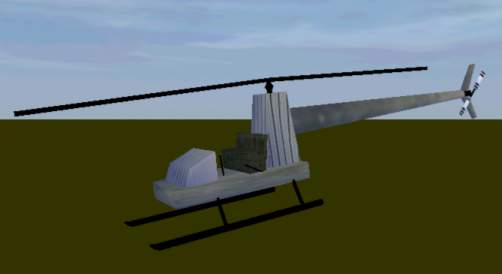
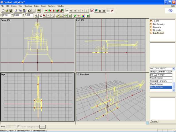
Así que vamos a echar un vistazo a nuestro modelo. Como he dicho anteriormente, este es un modelo muy simple y no estoy perdiendo tiempo valioso hacer un modelo 3D exacto de un helicóptero para esta simple lección. Así que sólo quite las ruedas y alerón al modelo de la lección 2 y añadí una sección de cola, patas y rotores. También algunos cambios en la LOD de Geometría para coincida con el nuevo modelo de la LOD principal:
El nuevo modelo visto desde el Bulldozer
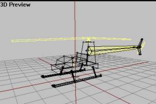
El modelo de la LOD de Geometria
Sí, los modelos de ejemplo de lección que vas recibiendo son más y más feo, lo sé. Pero el punto principal es aprender de ellos. Empecemos:
+ Descarga el modelo de ejemplo junto con las texturas y extras aqui. + Poner los archivos en una nueva carpeta llamada "firstheli" en el directorio donde esté instalado el Bulldozer (generalmente en la unidad P:/)
Entonces enciende el O2 (Object Builder) y el Bulldozer, y mira bien el modelo. Esto es todo muy básico y se puede crear un modelo de este tipo con las cosas simples aprendidas en la lección 1 y la lección 2. Son unas pocas cajas y cilindros con texturas sobre ellos. En la LOD de Geometría se han modelado solo las partes clave y a todas se les ha aplicado peso. Pienso que todo esto debería ser familiar para ti. Ahora, vamos a empezar, tenemos un largo camino por delante.
Fire Geometry
Vamos a ir avanzando a través de todas los LODs normales para un addon de helicóptero y vamos a comenzar con la Geometría la Fuego. La geometría de fuego es algo que tienen la mayoría de los Addons, pero por simples razones no he hablado de ella en las lecciones anteriores. La Fire Geometry es muy similar a la geometría "normal", pero esa Geometría se utiliza para la detección de colisiones (golpes del addon con otros objetos o terreno), la geometría de fuego se utiliza para comprobar si es impactado por una bala, granadas, cohetes, etc.
Así que sin la Fire Geometry, las balas podrían pasar a través del addon sin golpear el modelo? Bueno, no es cierto. Porque si el OFP/ARMA no puede encontrar la Geometría de Fuego, utiliza automáticamente la geometría normal en su lugar. Genial, ¿no es cierto? Así que no necesitamos Fire Geometry entonces? Sí, lo necesitamos. Observe que las estructuras (o componentes, si se quiere) en nuestro son muchos bloques y no se ajustan bien a sus partes reales en la LOD en "0.000"; también conocida como la estructura principal del cuerpo con la placa inferior, asientos, panel frontal, etc es sólo un gran bloque en la LOD de geometría. Esto significa que se puede disparar una bala cerca, pero no directamente en la estructura del vehículo dentro del juego y todavía golpear el helicóptero. Y eso es un poco irreal, ¿no es cierto?
Pero entonces por qué no hacer una LOD de Geometría más detallada? El hecho es que con más detalle en la Geometry LOF significa más carga en la CPU. Recuerde que la detección de colisiones es algo que se hace todo el tiempo en el juego, mientras que la comprobación de impactos de fuego se realiza sólo cuando se dispara! De esta manera podemos tener un modelo de bajo detallado para la LOD de Geometría y un modelo con detalle más alto para la geometría del fuego. La conclusión es que una LOD de Geometría detallada es más pesada que una Geometría de Fuego.
Si no entendiste todas los precauciones antes, entonces no puedo hacer mucho al respecto. No es tan importante entenderlo en este momento, solo tiene que hacer lo que digo y todo saldrá bien . El contenido de la LOD de Geometría de Fuego será similar a la del límite de detección de la Geometría pero con más detalle. Para evitar la creación de más (y ya que nuestro principal modelo es tan simple de todos modos), vamos a utilizar algunas partes del modelo principal y algunos de nuestra LOD de Geometría (puedes encontrar tipos de uno y otro a mitad de la lección, si lo deseas).
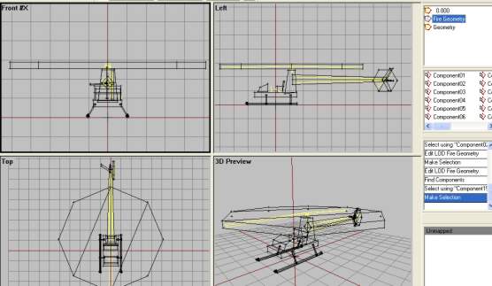
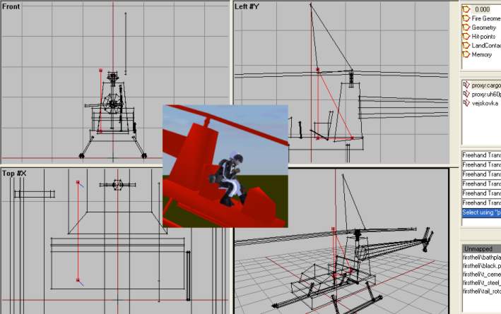
+ Iniciamos el O2 y abrimos nuestro modelo de helicóptero + Ir a nuestra LOD principal (0.000) y pulsar F2. Mientras mantienes pulsada la tecla Ctrl, arrastra alrededor de un vértice en cada estructura y seleccionar todas las estructuras como en la imagen siguiente. Asegúrate de llegar a todos ellos y solo ellos (No olvide el estabilizador horizontal de la cola).
+ Presiona Ctrl + C para copiar las estructuras seleccionadas. + Crear una nuevo LOD y cambiar el tipo a "Fire Geometry" + En la nueva LOD, pulsa Ctrl + V para pegar las estructuras copiadas en el paso uno. + Ahora necesitamos el cono de cola (tailboom). La de la "0.000" es demasiado detallada, y es un desperdicio de potencia del CPU, pero la de Geometry LOD no tendrán ningún problema. Así que ir a la LOD de Geometría, seleccionar el cono de cola, Ctr + C de nuevo, ir a la Fire Geometry y pegar allí. La geometría de fuego debería tener este aspecto:
Ahora necesitamos algo para representar los dos rotores. Los que están en la LOD principal no pueden ser utilizados (lo explico más tarde...) y las del Geometry son mucho más cuadradas. Ellos cubren más que los lugares hacer de verdad. Así que hay que hacer dos estructuras cilindricas planas, y vamos a comenzar con el rotor principal.
+ Activar la Vista Superior y pulsar F8. Escriba 8 en el "Segments Radius" y pulsa OK. Escala y mueve el cilindro en su lugar de modo que se parezca a esto:
+ Ahora el cilindro para el rotor de cola. Activa la vista Lateral, pulsa F8 y enSegments Radius pon 6. Pulsa OK + Ahora escala y posicionalo para cubrir el área de rotación para el rotor de cola de esta manera:
Ahora la Geometría de Fuego básica está casi lista. Hemos definido las áreas que el motor de OFP utilizará para comprobar si nuestro modelo es impactado o no. Pero tenemos que hacer algunas correcciones primero. En primer lugar, las estructuras de Geometría de Fuego no pueden tener texturas (por qué lo harían, son invisibles). Y las partes que copiamos de la LOD "0.000" tienen texturas que hay que eliminar. Recuerde que en la lección 1 aprendimos cómo asegurarse de que O2 tiene las rutas de texturas adecuadas para nuestro modelo? Utilizamos Ctrl + LMB (doble clic) sobre las texturas de la lista para autoseleccionar todas las estructuras que tengan esa textura, activa una vista y presiona "E"? Si no, mire la última parte de texturización en la lección 1 ahora.
Debemos hacer como en la lección 1, pero en lugar de asegurarse de que la ruta en el cuadro de edición inferior es correcta, eliminar y presiona Aplicar, y a continuación, en OK. Esto eliminará la textura de las estructuras seleccionadas. Hacer este proceso para todas las texturas que figuran en la Fire Geometry hasta que todas las texturas desaparezcan. Además, cuando copiamos la parte del cono de cola de la Geo LOD a la Fire Geo, nos copió también el nombre de selección. En Fuego Geo, Seleccione el nombre de selección (llamado component04 creo) y eliminarlo (RMB y eliminar).
Al igual que en la LOD de Geometría, todas las estructuras tenían un nombre de selección para ellas, llamadas Component01, 02, etc. Tenemos que tener esto en la Fire Geo también. Pero en vez de hacerlo manualmente, podemos hacer que O2 lo haga automáticamente por nosotros (por eso quería eliminar el Component04 del cono de cola para evitar que O2 se confunda). Así, estando en la fire Geo LOD y sin ninguno de los componentes seleccionados, ir a "EstructuraStructure->Topology->Find Components" en el menú. Todas las piezas serán ahora asignados a la selección "ComponentXX" (debería ser 15 en total).
Ahora hemos terminado con la carga de la Fire Geometry. Debería tener este aspecto:
O2 vista de la Fire Geometry LOD.
Vista de Bulldozer. Asegúrese de que todas las texturas se han ido.
Ahora pasemos al siguiente punto.
HitPoints LOD
Ademas de tener un Fire Geo LOD para saber cuando el modelo se ve afectado por el disparo de un arma, el motor de OFP es capaz de saber qué partes son golpeadas. Es el tanque de combustible? ¿El motor? De esta manera podemos tener daños más realistas para nuestro modelo. Pero en que formas las estructuras de la HitPoints LOD pueden parecerse? Como puedes pensar, deben ser similares o casi idénticas a las de la geometría de fuego. Por lo general, los editores de Addons tienen algún diferencia entre las estructuras de la Fire Geometry y la HitPoints LOD, pero no es importante para esta lección. Así que nos limitaremos a utilizar las estructuras de nuestra Fuego Geo LOD y marcar algunos nuevos nombres de selección. Sigamos:
+ Ir a la Fire Geo Lod y pulsar Ctrl + A para seleccionar todo su contenido. A continuación, pulse Ctrl + C para copiar. + Hacer una nueva LOD y cambiar a HitPoints en la lista de propiedades. En esta LOD, pulse Ctrl + V para pegar las estructuras en ella. + Ahora eliminar todos los nombres de selecciones (Component01, 02, 03, etc.), de modo que no queden nombres de selecciones en nuestra HitPoints LOD. Se parece a esto después:
HitPoint LOD sin nombres de selecciones.
Ahora tenemos que marcar algunos nombres de selección en esta LOD que tendrán poco uso. Simplemente le decimos OFP que parte es el motor, cual el rotor principal, etc. mediante la selección de las estructuras y la creación de nombres de selecciones para ellos. Hay un montón de nombres de selecciones que se pueden utilizar en esta LOD, pero sólo consentrate en los más comunes:
+ Elekronika: Sistemas Electrónicos. + Motor: Motor Principal. + Mala vrtule: Rotor de Cola. + Velka vrtule: Rotor Principal. + Ocas: Cono de Cola. + Stabilizator: Aleta de la Cola Horizontal + Palivo: Tanque de Combustible + Trup: Fuselaje Principal + Svetlo L: Luz Izquierda + Svetlo P: Luz Derecha + Pilot: Piloto + Cargo: Pasajero
Así que manos a la obra:
+ Con F2, seleccione el bloque delante de los asientos y crear una selección llamada "elekronica". + A continuación, seleccione el bloque alto detrás de los asientos (el que sostiene el rotor principal arriba) y crear una selección llamada "motor". + Luego, seleccione el cilindro del rotor de cola y el nombre de "mala vrtule". + Seleccione el cilindro del rotor principal y llamalo "velka vrtule" + Seleccione el tubo de cola y el estabilizador vertical, dejando de lado al horizontal. Nombrarlos "ocas". + Seleccione el estabilizador horizontal y llamarlo "stabilizator". + Seleccione la sección del asiento y lo llaman "palivo" (sí, se sientan en el depósito de combustible). + Seleccione la placa de base, y todas las 6 partes del tren de aterrizaje y los llamará "trup".
Ahora, para la última parte de la lista de nombres de selección de arriba, tenemos que añadir algunos vértices (bueno, hemos utilizado todas nuestras estructuras ya, no tenemos). Necesitamos un vértice simbolizando al piloto, uno para el pasajero y dos en la parte delantera del modelo que representan las posiciones de los faros (sí, nuestro heli tendrá luces de trabajo!).
+ En la vista lateral, colocar un vértice justo en frente de la placa inferior. + En la vista frontal, hacer una copia de la misma (shift + moverse con el eje X bloqueado) y colocarlo a la misma distancia de la línea central. A continuación, seleccione cada uno de ellos y llamelos "L svetlo" y "P svetlo". Quedaría asi:
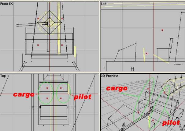
+ A continuación, los dos últimos, piloto y de carga (pasajeros). Coloque 4 vértices en el área del asiento como en la siguiente imagen. Cada posición tiene dos vértices (mayor probabilidad de seleccionar al piloto o al pasajero).
Uff, un montón de nombres aquí. Pero ahora hemos terminado con HitPoints LOD. Continuamos...
LandContact LOD
La siguiente LOD es LandContact y es algo fácil. El nombre delata su función por lo que vamos a hacer esto sin hablar demasiado. La idea es colocar 5 vértices debajo del helicóptero, dos en cada tren de aterrizaje y un quinto en el centro de la parte trasera (para que sea más difícil que el heli se vuelque hacia atrás en los malos aterrizajes, supongo). Es muy fácil, sólo 5 vertrices en el mismo plano (utilice el bloqueo del eje X cuando este copiandolos). Es muy fácil de hacer y similar a los 4 vértices que pusimos debajo las ruedas del coche en la Lección 2. Hacer una nueva LOD, cambiarla "LandContact" y empezar a colocar vertrices. A continuación la imagen con las ubicaciones finales.
Muy fácil, ¿no? Y no hay nombres de selecciones necesarias en absoluto. Es extraño que, pero en todos los Addons que he visto; ninguno con nombres de selecciones para la LandContact LOD. Siguimos a continuación.
Memory LOD
Y aquí estamos de vuelta con un nuevo episodio de "Creando un Chopper" aquí en Discovery, Soy Marcos Eavens y hoy con nosotros... ehh..oh, no importa. Miren el show gente!
Ok, listos para lo grande? Esta es la más importante de las LOD (creo). Vimos una buena cantidad de diferentes nombres de vertrices. Si has seguido todas las lecciones, debes saber que aquí es donde ponemos cosas como posiciones para el jugador dentro y fuera, definiciones de eje (axis-definitions), como para el volante en la lección 2, y un montón de otras cosas. Pero ya estamos listos para despegar así que no te des por vencido ahora.
Aquí tienes una lista de todas los nombres de selección que necesitamos:
+ cerveny pozicni blik: Luz Roja Posicional Intermitente + zeleny pozicni blik: Luz Verde Posicional Intermitente + L svetlo: Luz Izquierda + P svetlo: Luz Derecha + konec L svetla: Luz de Extremo Izquierdo + konec P svetla: Luz de Extremo Derecho + mala osa: Eje del Rotor de Cola + velka osa: Eje del Rotor Principal + osa vejskovky: Eje del Elevador (Estabilizador Horizontal) + zamerny: Punto de Objetivo / Línea de Visión + pos driver: Posición de Entrada/Salida de Piloto + pos cargo: Posición de Entrada/Salida de Pasajeros
Así que vamos a trabajar.
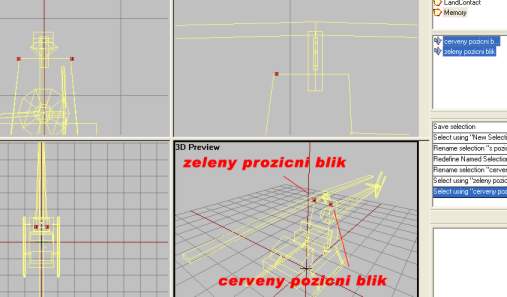
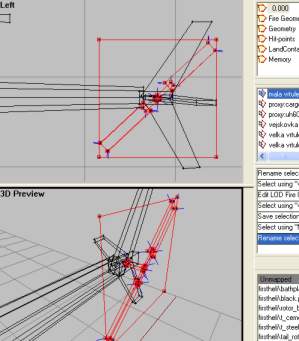
+ Crear una nueva LOD y cambiala a Memory LOD. Vamos a empezar con la parte de arriba de la lista anterior. + Coloca dos vértices en cada lado del heli y marcalos como "Blik cerveny pozicni" y "zeleny pozicni blik", como en la imagen de abajo.
+ Coloque cuatro vértices en la posición frontal para indicar la luz de posición (dos luces, comienzo y final). Asi:
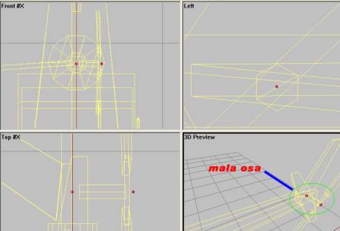
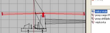
+ El siguiente es el eje del rotor de cola, "mala osa". Coloque dos vértices con una distancia entre sí como en la siguiente imagen. Asegúrese de que está en el centro del eje del rotor de cola en el modelo de la LOD principal ("0,000") y que la línea que crea en el eje sea paralela al suelo. Seleccione ambos vértices y nombralos como "mala osa".
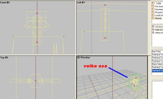
+ Lo mismo para el eje del rotor principal, "velka osa". Dos vértices colocados directamente uno encima del otro en la vista lateral y en el centro de eje del rotor del modelo real del helicóptero. Asi:
+ Eje para el estabilizador horizontal, llamada «vejskovky osa", es sólo un único vértice colocado como en este, en el centro del modelo en la sección de cola. Insertarlo en la vista lateral para hacer que aparezca en el centro cuando se vea desde la vista frontal.
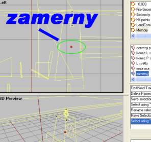
+ Y para la línea de visión, sólo hay que poner un solo vértice en el interior del bloque del motor con el nombre de "zamerny". Insertarlo en la vista lateral para hacer que aparezca en el centro cuando se vea desde la vista frontal.
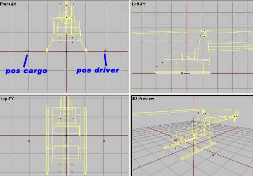
+ Y finalmente dos vértices que te deben sonar familiar de la lección 2, la posición de entrada para el "pos driver" y "pos cargo". Al igual que en la lección 2, aquí está:
Ya hemos terminado con la Memory LOD. Sigamos adelante
Prepando el Modelo Principal de la LOD "0.000"
Ok, no esta oportunidad no vamos a crear una nuevo LOD porque solo tenemos que hacer algunos cambios en la LOD original "0.000", para que se vea bien durante el vuelo. Tenemos que marcar algunos nombres de selección e incluso aplicar una o dos texturas(!), pero nada que deba dar miedo. Lo terminaremos pronto, lo prometo.
Como de costumbre, una lista de todos los nombres de selecciones que tendremos que aplicar. Por supuesto, hay más, pero sólo necesitamos estos para nuestro modelo de tutorial:
+ vejskovka: Estabilizador Horizontal + mala vrtule: Rotor de Cola entero + mala vrtule blur: Cara del Rotor de Cola con el desenfoque de la Textura + mala vrtule staticka: Rotor de Cola, versión estática. + mala vrtule textura: Rotor de Cola, sólo el desenfoque de la Textura + velka vrtule: Rotor Principal rntero + velka vrtule blur: Cara del Rotor Principal con el desenfoque de la Textura + velka vrtule staticka: Rotor Principal, versión estática. + velka vrtule textura: Rotor Principal, con el desenfoque de la Textura
Además de que vamos a tener dos proxys, uno para el piloto y otro para el pasajero.
Vamos a seguir adelante, ¿de acuerdo?
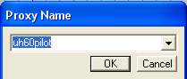
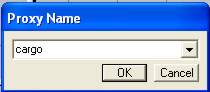
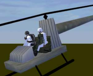
+ Ir a la LOD "0.000" y usa F2 para seleccionar el estabilizador horizontal de la cola. El nombre de "vejskovka". + Ahora los proxys; había dos modelos sustitutos de la demo del zip que descargaron al comienzo de la Lección. Al igual que en la Lección 2, ponerlos en la carpeta "data3d" del Bulldozer. Si usted no sabe lo que son los proxys, mire la Lección 2. + Al igual que en la Lección 2, elija Insertar Proxys en el menú. Vamos a insertar uno para el "piloto" y otra para "carga" (pasajero), moverlos a su sitio y use el Bulldozer para ver si los proxys están bien colocados en el modelo. El proxy para el piloto se llama "uh60pilot" y el otro se llama "cargo". Use estos nombres en el "Insert Proxy Dialog". Aquí hay algunas imágenes del proceso:
El resultado final. No se preocupe si no se ve bien, mi modelo no se ajusta perfectamente a estos proxys (yo tuve que girar el piloto un poco hacia adelante sólo para poner sus pies en el suelo y el proxy de carga se mete un poco en el interior del asiento). Pero me parece que no es demasiado relevante para este modelo tutorial.
Genial, los proxys están listos. Bien. Ahora, vamos por el resto de las opciones de la lista de nombres de selección. Pero primero tenemos que hacer un poco de texturización, estoy asustado. Si usted ha mirado en las texturas en la cremallera, va a ver que cuando los rotores están girando a toda velocidad, el modelo de rotor se sustituye con una textura borroneada que gira a velocidad lenta para hacer que parezca que su rotor gira a altas revoluciones. Sí, es todo un fraude. Pero lo harás. Hagámoslo:
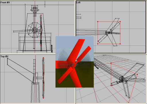
+ Ir a la vista superior, hacer click en create->plane. Establecer Tamaño de X e Y en 10 y pulsar Aceptar. Justo después de apretar OK, presiona F6 para hacer una "double faced face" (cara de doble cara) del nuevo plano. Ahora anular la selección del plano y vuelva a seleccionarlo (hay que hacer esto, porque después de presionar F6 sólo un lado del plano se selecciona). Ahora tenemos un plano de doble cara que podemos texturar. + Presiona A y carga la textura llamada "rotorblur.paa". Dibújala alrededor del avión y aplicala con "B". Luego mueve el plano de modo que se encuentre en la trayectoria de giro de las palas del rotor, como este.
+ Ahora vamos a utilizar una copia de las mismas texturas del plano para el rotor de cola. Así que seleccione el rotor principal con F2 y pulse Ctrl + C para copiar. Pegar la nueva copia, escalar y rotar para que se parezca a esto:
Ahora escucha con mucho cuidado y sigue mis próximas instrucciones al pie de la letra:
+ Usa F2, Ctrl y LMB, selecciona el rotor principal con textura plana, las palas del rotor principal, el eje del rotor principal y sus dos brazos. Nombra la selección como "velka vrtule".
+ Ahora selecciona sólo la textura plana del rotor principal y nombrala "velka vrtule blur". + Selecciona sólo las palas del rotor principal y llamalas "velka vrtule staticka". + Ahora selecciona sólo la textura plana del rotor principal (de nuevo, lo sé) y dale el nombre de "velka vrtule textura" (no estoy seguro si esto es obligatorio, pero hazlo de todos modos para estar seguro). + Ahora, para el rotor de cola (es casi lo mismo piensn solamente en "mala" en lugar de "velka", pero aquí va de todos modos). + Seleccione la textura plana del rotor de cola, las palas del rotor de cola, la sección media y el eje del rotor de cola. Nombralas "mala vrtule"
+ Seleccionar sólo la textura plana de cola y nombra "mala vrtule blur" + Seleccionar las dos palas del rotor de cola y la parte media y llamar a esas 3 estructuras "mala vrtule staticka". + Seleccionar sólo el plano texturado de cola (de nuevo) y llamarlo "mala vrtule textura"
Y estamos cerca del 90% finalizado de nuestro heli ahora mismo! Lo prometo.
Nuestra LOD "0.000" está toda lista.
"View Cargo" y "View Pilot" LODs
Ok, sólo este último poco y terminamos. Pero hay algo más que creo no he hablado en mis lecciones hasta ahora y eso son las LODs opcionales llamadas "View Pilot" y "View Cargo". Usted ve, cuando usted es el piloto o pasajero y está mirando con vista de primera persona en el helicóptero, no ve todo el modelo. Usted solo ve la parte delantera del helicóptero, el detalle de la cabina del piloto, tal vez los pedales y las partes del rotor que giran. Pero hay piensa que algunas partes nunca se ven, al igual que las partes del eje del rotor principal y absolutamente nada de la sección de cola. El problema es que si el equipo tiene que dibujar el modelo entero incluso cuando usted no puede ver la parte trasera del modelo en la vista en primera persona, está perdiendo potencia de su CPU.
Esto tiene otro tema también. A veces queremos tener cabinas muy detalladas y los detalles pueden ser difíciles de apreciar en la vista de 3ra persona. Así que para hacer más rápida la vista externa (más fotogramas por segundo / FPS), podemos dejar de lado algunos detalles en la LOD normal ("0,000") y aumentar el detalle en las LODs " View Pilot/Cargo ".
Así que básicamente hacemos nuevos LODs llamados " View Pilot" y "View Cargo", que contiene sólo las cosas de "0.000" que son visibles por el piloto / pasajero. Así es como:
+ Ir a la LOD "0.000" y seleccionar todo (Ctrl + A), pulse Ctrl + C para copiar todo. + Hacer una nueva LOD y cambiarla a " View Pilot". En esa, pegar (Ctrl + V) el material copiado allí. + Ahora trata de pensar en los detalles no se pueden ver desde la cabina. Vamos a eliminarlos. Aquí está mi lista: cono de cola y toda la sección de cola, el eje del rotor principal con los dos brazos (no estoy seguro con el tren de aterrizaje, así que lo dejó permanecer allí). Usted no tiene que eliminar los nombres de selección a pesar de que se haya eliminado las estructuras a las que apunten. Aquí es lo que he eliminado y cómo se ve después:
+ También necesitamos una LOD para el proxy de carga/ pasajero. Primero en la "View Pilot" LOD, seleccionar y copiar todo. Hacer una nueva LOD y lo llamarla "View Cargo" y pegar, por lo que las LODs "View Pilot" y "View Cargo" son idénticas. Ellos son los mismos ya que lo que ven los pasajeros es el mismo que puede ver el piloto.
Cómo el "View Pilot" y el "View Cargo" deben ser similares en el Bulldozer después de eliminar algunas estructuras.
Ok, esto sería todo. Pero una última cosa. Cuando hice mi primer modelo de helicóptero, tenía un problema. El paisaje detrás de la modelo comenzó a parpadear o desaparecer por ninguna razón. He publicado el problema en los foros y obtuve una respuesta sobre cómo resolverlo; haciendo un LOD denominado " View Geometry" que tenía el mismo contenido que la LOD "0.000". No puedo decir que entiendo por qué esto iba a funcionar, pero funcionó de todos modos. Por lo que necesita una también. Simple, ve a "0.000", selecciona y copia todo. Hacer una nueva LOD y cambiarla a " View Geometry". Pegarlo todo ahí. Y eso es todo, nada más.
Adivina qué, esa es la última de las LODs. Ahora estamos listos con nuestro modelo de helicóptero y ya preparado para volar. Pero primero, una mirada al archivo de configuración. ¡Sigamos!
El Archivo de Configuración
Conseguir que los archivos de configuración trabajen de la forma que se desea por lo general involucra algunos fallos graves del OFP, le he pegado varios gritos a la PC junto con el sacrificio de una cabra santa para el Señor Oscuro con la esperanza de que BIS libere un editor de archivos de configuración con un depurador de bugs integrado. Mientras tanto estamos obligados por lo general a usar el buen bloc de notas junto con un conocimiento básico de programación en C ++. Así que no voy a decirles cómo hacer un “config”, yo sólo le puedo hablar de lo que he utilizado para este tutorial, hasta que usted entienda cómo hacer su magia.
La parte más interesante del archivo de configuración.
Como se puede ver, hay muchas características y atributos conocidos por aquí, al igual que el "model =", "transportSoldier" y "i displayname " (si no, vea la Lección 1 y 2). He utilizado la clase UH60 para obtener las características básicas que tiene un helicóptero, eliminado al artillero (hasGunner = 0), lo desaceleré un poco (maxSpeed=130), para un solo pasajero (transportSoldier = 1) y la convertí en un avión civil (TCivilian, que significa "tipo Civil”). Si no hubiera heredado la clase UH60, tendría que añadir muchos más atributos que simplemente sería confuso en este momento para un principiante.
Nota: Este archivo de configuración se probó en v1.75 y superior. Para hacer el trabajo correctamente con el heli en la v1,46 e inferiores, es posible que tenga que eliminar la clase “CfgModels” nombradas en la config. Simplemente elimine esa sección y funcionará perfectamente.
Ok, basta de charla. Vamos a conseguir que esta cosa se suspenda en el aire, a continuación...
Final
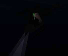
OK, listo para volar? Entonces solo use PBOTool para comprimir la carpeta y guardala como "firstheli.pbo" en la carpeta Addon de OFP. Puedes encontrarlo en Vacio-> Aire ->"My First heli" en el editor. Vamos a probarlo, tanto en el día y como en la noche para ver si las luces funcionan correctamente. Aquí están algunas fotos de el dentro del juego:
Y ya está listo, soldado. Puede sentirse orgulloso porque acaba de construir su primera helicoptero funcional para el OFP!
Algunos pueden sentirse inseguros ahora mismo, tal vez este esperando una guía completa para hacer instrumentos de la cabina, sonidos personalizado o cargados con armas. Pero recuerde que este es un tutorial simple y que el objetivo era obtener las bases en la fabricación de un helicóptero para el OFP. Y yo le he dicho lo básico, como lo son las LODs necesarias, los nombres de selección más comunes y algunos consejos y sugerencias.
PD: Usted puede haber notado que el helicóptero puede disparar cohetes (de una manera un tanto extraña). Esto se debe a que se utiliza la clase UH60 y este heli tiene cohetes. Así que ahora usted puede usar lo que ha aprendido y hacer algunos lanzadores de cohetes para el heli, en la Memory LOD haga un vértice en cada lanzadera de cohetes y nombrelos " L Raketa" y "P Raketa" para hacer el fuego de cohetes desde esas posiciones en vez del centro estándar del modelo base. Pero siempre depende de ti y tu práctica.
Como de costumbre se puede descargar el modelo terminadoaqui. Cualquier comentario, preguntas, informes de errores pueden hacerlo al correo habitual; brsseb@hotmail.com.
Érase una vez una era oscura en la que los jugadores eran conducidos como ganado por rígidos caminos de juego. Bohemia Interactive fue la revolucionaria desarrolladora que los liberó.
Hello, and welcome back to yet another lesson. This time you get to make your very own helicopter. And if you`ve followed the previous lesson this should be a walk in the park. Therefore Im not going to be that step-by-step as I was in the beginning lessons (aka wont repeat over and over how to do simple stuff like texturing, naming selections and LODs and stuff). But dont worry, we are keeping things simple as usual. I will provide a simple model and textures and I will guide you trough each step in getting the heli airborne.
So, what skills do you need then. Lets see:
+ OFP (daahhh), O2 and Bulldozer + Basic understanding of the O2 interface + Having fully understud stuff from lesson1 (like creating LODs, selections etc) + Also, if you made it through lesson 2, this should be an easy lesson. + PBOTool and TexView
Ok, thats the most important things. Now move on and have a look at the model we are going to turn in into a chopper.
The basic model
So lets have a look at our model. As Ive told earlier, this is a VERY simple model and Im not wasting valuable 3d model time making an accurate 3d model of a heli for this simple lesson. So I just stripped the model from lesson 2 for wheels and spolders, added a tail section, skids and rotors. Also some changes to the geometry LOD to go with the new model in the main LOD:
The new model view from Bulldozer
The models Geometry LOD
Yes, the lesson example models keep getting uglier and uglier, I know. But you`ll learn from it, thats the main point. Lets get started:
+ Download the example model with textures and extras aqui. + The files go in a folder named "firstheli" in the dir where Bulldozer is installed
Then fire up o2 and Bulldozer and check out the model. Its all very basic stuff and you can create such a model with the simple stuff learned in lesson 1 and lesson 2. Just blocks or cylinders with textures on them. In the geo lod key parts have been modelled and the whole thing has been applied wheight to. All thinks that should be familiar to you now.
Now, lets gets started, we`ve got a long journey ahead.
Fire Geometry
Im going to walk you trough all the normal LODs fround in a heli addon and we will start with Fire Geometry. Fire Geometry is something that most addons have, but for simple reasons i havent talked about it in the previous lessons. Fire Geo is much like "normal" Geometry, but where Geomery is used for collision detection (addon bumping into other objects or terrain), Fire geometry is used for checking if it is hit by a bullet, grenade, rocket etc.
So without Fire Geo, bullets could just pass trough the addon without hitting the model? Well, not true. Because if ofp cant find Fire Geometry, is automatically used normal Geometry instead. Great, isnt it? So we dont need Fire geo then? Yes, we need it. Notice that the structures (or components, if you like) in our model is very blocky and dont fit good to their actual LOD parts in "0.000"; aka the main body structure with bottom plate, seats, front panel, etc is just a big block in the geo lod. That means that you can shoot a bullet close to, but not directly on, the airframe ingame and still hit the helicopter. And thats a bit unreal, isnt it?
But why not make the geo lod more detailed, then? The fact is that more detail in the geo department means more load on the CPU. Remember that collision detection is something done all the time ingame, while checking for firehits are done only when something is fired! That way we can have a low-detailed model for the Geometry lod and a higher detail model for the Fire Geometry. The bottom line is that Geometry detail is more expensive than Fire Geometry.
If you dont understod all the above, then dont care much about it. Its not that important to understand, right now you just do what I say and all will be well:). The content in the Fire Geo lod will be similar to the Geometry LOD but with more detail. To avoid creating to much (and since our main model is so simple anyway), we will use some parts from the main model and some from our Geo lod (sort of meeting eachouther on the half-way, if you like).
+ Fire up 02 and open our helimodel + Go to our main lod (0.000) and hit F2. While holding down ctrl, drag around a vertex in each sturture and select all of the structures in the picture below. Make sure to get them all and just them (Dont forget the horizontal stabilizator on the tail).
+ Hit Ctrl+C to copy the selected structures. + Create a new LOD and change the type to "Fire Geometry" + In the new LOD, hit Ctrl+V to paste the copied structues into that one. + Now we need the tailboom. The one in "0.000" is too detailed, too much wasted CPU power, but the one in Geometry LOD will do just fine. So go to Geo LOD, select the Tailboom, Ctr+C, back to Fire Geo Lod and past it there. So far Fire Geometry should look like this:
Now we need something to represent the two rotors. The ones in main LOD cant be used (tell you later..) and the ones in Geo is to much square-ish. They cover more that the places do for real. So we must make two flat cylinderstructues and we will start with the main rotor.
+ Make Top view active and hit F8. Type 8 in the "Segemts Radius" and hit ok. Scale and move the cylinder inplace so that it looks like this:
+ Now the cylinder for the tail rotor. Make sideview active, hit F8 and in the Segments Radius type 6. Hit ok + Now scale and position it to cover the rotation area for the tail rotor like this:
Now basic Fire Geometry is almost done. We now have defined the areas that the ofp engine will use to check if our model is hit or not. But we need to do some fixes first. First of all, structures in Fire Geo cant have textures (why would they, its invisible!). And the parts you copied from "0.000" LOD have textures on them that we must remove. Remeber from lesson 1 we learned how to make sure that o2 got the right texture paths for our model? We used ctrl+LMB (doubleclick) the listed textures to autoselect all structures that had that texture, activated a view and hit "E"? if not, see last part of texturing in lesson 1 now.
You must do like in lesson 1 but instead of making sure that the path in the lower editbox is right, we delete it and hit apply, then OK. This will remove the texture from the selected structures. Do this prosess for all the listed textures in the Fire Geo untill all textures are gone. Also, when we copied the tail boom part from Geo LOD to the Fire Geo, we got its named selection with us. In Fire Geo, Select the named selection (called component04 I think) and delete it (RMB and delete).
Like in Geometry LOD, all structures had a named selection for them, called Component01, 02 etc. We must have this in Fire Geo too. But instead of making them manually, we can make o2 do this automatically for us (why I wanted you to delete the Component04 for the tailboom to avoid o2 getting comfused). So, while in the Fire Geo LOD and no components selected, find "Structure->Topology->Find Components" from the menu. All parts will now be assigned a "ComponentXX"-selection (should be 15 in total).
Now we are done with the Fire Geo LOD. It should look like this now:
O2 view of the Fire Geo LOD.
Bulldozer view. Make sure all textures are gone.
Now lets move on.
HitPoints LOD
In adition to having a Fire Geo LOD for knowing when the model is hit by gun fire, the ofp engine is capable of knowing WHAT parts are hit. It is the fueltank? The engine? That way we can have more realistic damages for our model. But how will the structures in HitPoints LOD look like? As you may think, it should be similar or near identical to the ones in the Fire Geometry. Usually addon makers have some differencen between the stuctures in Fire Geo and Hitpoints LOD, but its not important for this lesson. So we will just use structures from our Fire Geo LOD and make some new named selections. Lets move:
+ Go to Fire Geo LOd and hit Ctrl+A to select everything in it. Then hit Ctrl+C to copy. + Make a new LOD and change it to HitPoints from the property list. In this LOD, hit Ctrl+V to paste the structures in it. + Now delete all the named selections (Component01, 02, 03 etc) so that there are no named selections in our HitPoints LOD. It will look like this afterwards:
HitPoint LOD with no named selections.
Now we must make some named selections or this LOD will have little use. Simply we tell ofp like what part is the engine, what is the main rotor, etc by selecting structures and creating named selections for them. There are lots of named selections that can be used in this LOD, but we will just consentrate on the most common ones:
+ Elekronika: Eletronic systems. + Motor: The engine itself. + Mala vrtule: Tail rotor. + Velka vrtule: Main rotor. + Ocas: Tail Boom. + Stabilizator: Horizontal tail fin + Palivo: Fuel tank + Trup: Main fuselage + Svetlo L: Left light + Svetlo P: Right light + Pilot: Pilot + Cargo: Passenger
So lets get to work:
+ Using F2, select the block in front of the seats and create a selection for it called "elekronica". + Next select the Tall block behind the seats (the one holding the main rotor up) and give it a selection called "motor". + Then select the tail rotor cylinder and name it "mala vrtule". + Select main rotor cylinder and call it "velka vrtule" + Select the tail boom and the vertical stabilizator, leaving the horizontal one out. Name them "ocas". + Select the horizontal stabilizator and call it "stabilizator". + Select the seat section and call it "palivo" (yes, they sit on the fuel tank). + Select the bottom plate, and all 6 parts of the landing gear and call them "trup".
Now for the last parts of the named selection list above, we need to add some vertices (well, we have used all of our structures now, havent we). We need a vertex sympolising the pilot, one for the passenger and two at the front of the model representing the headlight positions (yes, our heli will have working lights!).
+ In side view, place a vertex just in front of the bottom plate. + In front view, make a copy of it (shift+move with x-axis locked) and place them equal distances from the centerline. Then select each one and call them "L svetlo" and "P svetlo". Like this:
+ Then the last two ones, Pilot and Cargo (Passenger). Place 4 vertices in the seatarea like in the next picture. Each position has two vertrices (greater chance of hitting the pilot or passenger).
Phew, lots of names there. But now we are done with HitPoints LOD. Continue..
LandContact LOD
Next LOD out is LandContact and its an easy one. The name gives away its function so we`ll just do this without too much talk. The idea is to place 5 vertices beneath the heli, two under each landing gear and a fifth one at the rear center (to make it harder for the heli to tip backwards in bad landings, I think). Its very easy, just 5 vertrices on the same plane (aka use x-axis locking when crag_copying them). Its very easy to do and similar to the 4 vertices we put under the wheels of the car in lesson 2. Make a new LOD and make it "LandContact" and start placing vertrices. Here is a picture of the final placements.
Pretty easy, huh? And no named selections needed whatsoever. Strange that, but in all the addons Ive seen; no named selections for the LandContact LOD.
Next one then.
Memory LOD
And here we are back with another episode of a "Chopper is born" here on Discovery, Im Mark Eavens and today we`re....ehh..oh, never mind. Watch the show, people!
Ok, ready for the "Big One"? This is the most important LOD (I think). Its got lots of different named vertrices. If you followed all the lessons you know that here is where we place stuff like in and out positions for the player, axis-definitions (like for the steeringwheel in lesson 2) and alot of other things. But we are soon ready to take off so dont give up now.
Here is a list of all the named selections we need:
+ cerveny pozicni blik: Red positional blinker + zeleny pozicni blik: Green positional blinker + L svetlo: Left light + P svetlo: Right light + konec L svetla: Left light end + konec P svetla: Right light end + mala osa: Tail rotor axis + velka osa: Main rotor axis + osa vejskovky: Axis of elevator (horizontal stabilizer) + zamerny: Aiming point/line of sight + pos driver: Pilot in/out position + pos cargo: Passenger in/out position
So lets get to work.
+ Create a new lod and change it to Memory LOD. We will start on the top of the list above. + Place two vertices on each side of the heli and make them "cerveny pozicni blik" and "zeleny pozicni blik", like the picture below.
+ Place four vertices in the front position to indicate light position (two lights, start and end). Like this:
+ Next is the Tail rotor axis, "mala osa". Place two vertices a distance from each other like in picture below. Make sure its in the center of the tailrotoraxis in the original model LOD ("0.000") and that the axis the lines create are parallell to the ground. Select both vertrices and name them "mala osa".
+ Same for the main rotor axis, "velka osa". Two vertrices placed directly on top of each other in sideview and in the center of the actual helicopter model`s rotorshaft. Like this:
+ Axis for the horizontal stabilizator, named "osa vejskovky", is just a single vertex placed like in this, in the center of the model in the tail section. Insert it from sideview to make it appear in the center when viewed from frontview.
+ And for the line of sight, just put a single vertex inside the engineblock and name ot "zamerny". Insert it from sideview to make it appear in the center when viewed from frontview.
+ And finally two vertrices that should sound familiar to you from lesson 2, the entering position for the "pos driver" and "pos cargo". Just like in lesson 2, here it is:
...And there we are done with Memory LOD. Move on
Preparing the main model LOD "0.000"
Ok, we are not creating a new LOD this time because we need to make some changes to the original LOD, "0.000", to make it look good while flying. We have to make some named selections and even apply a texture or two (!), but nothing too scarry. Soon done now, promise.
As usual, a list of all the named selections we will make. There are of course more, but we only need these for our tutorial model:
+ vejskovka: Horizontal stabilizator + mala vrtule: Entire Tail rotor + mala vrtule blur: Tail rotor face with blur texture + mala vrtule staticka: Tail rotor, static version. + mala vrtule textura: Tail rotor, only blur texture + velka vrtule: Entire Main rotor + velka vrtule blur: Main rotor face with blur texture + velka vrtule staticka: Main rotor, static version. + velka vrtule textura: Main rotor, only blur texture
In addition to that we will have two proxys, one for the pilot and one for the passenger.
Lets get going, shall we?
+ Go to "0.000" LOD and use F2 to select the horizontal stabilizator on the tail. Name it "vejskovka". + Now the proxys; there were two proxy models from the demo in the zip you got from the beginning of the lesson. Like in lesson 2, put them in the data3d folder in Bulldozer. If you dont know what proxys is, see lesson 2. + Just as in lesson 2, choose insert proxys from the menu. We will insert one for the "pilot" and one for "cargo" (passenger), move them into place and use Bulldozer to see if the proxys are well placed in the model. The one for the Pilot is called "uh60pilot" and the other is called "cargo". Use these names in the "Insert Proxy Dialog". Here are some shots from the prosess:
The final result. Dont worry if they dont look to good, my model dont fit these proxys perfectly (I had to rotate the pilot abit forward just to get his feet on the floor and the cargo proxy sits a bit inside the seat). But looks isnt too relevant for this tutorial model.
Great, proxys are done. Nice. Now for the rest of the named selections from the list above. But first we need to do some texturing Im affraid. If you have looked on the textures in the zip, you`ll see that when the rotors are spinning at top speed, the rotormodel is replaced with a blured texture rotating at slow speed to make it look like its the rotor spinning at high rpm. Yes, its all a fraud, Im affraid. But it will do. Lets do this:
+ Go to top view, click create->plane. Set both X and Y size to 10 and hit OK. Just after hitting OK, hit F6 to make a "double faced face" of the new plane. Now deselect the plane and the reselect it (you must do this, because after hitting F6 only one side of the plane is selected). Now you have a double sided plane that we can texture. + Hit A and load the texture named "rotorblur.paa". Draw it around the plane and apply it with "B". Then move the plane so that it lies in the rotation path of the rotor blades, like this.
+ Now we will use a copy of the same textures plane for the tail rotor. So select the main rotor with F2 and hit Ctrl+C to copy. Paste the new copy, scale and rotate it so that it looks like this:
Now listen very carefully and follow my next instructions to the point:
+ Using F2, Ctrl and LMB, select the main rotor textured plane, the main rotor blades, the main rotorshaft and its two arms. Name that selection "velka vrtule".
+ Now select only the main rotor textured plane and name it "velka vrtule blur". + Select only the main rotor blades and call it "velka vrtule staticka". + Now select only the main rotor textured plane (again, I know) and name it "velka vrtule textura" (not sure if this is mandatory, but do it anyway to be on the safe side). + Now for the tail rotor (any its the same think only with "mala" instead of "velka", but here it goes anyway). + Select the tail rotor textured plane, tail rotor blades, middle section and the tail rotor shaft. Name it "mala vrtule"
+ Select only the textured tail plane and name it "mala vrtule blur" + Select the two tailrotorblades and the middle section and call those 3 structures "mala vrtule staticka". + Select only the textured tail plane (again) and call it "mala vrtule textura"
And we are about 90% done with our heli right now! I promise.
Our "0.000" LOD is all done.
"View Cargo" and "View Pilot" LODs
Ok, just this last bit and we are done. But there is one more think I havent talked about in my lessons so far and thats the optional LODs called "View Pilot" and "View Cargo". You see, when you are the pilot or cargo looking in firstpersonview in the heli, you dont see the whole model. You see the front of the heli, cockpit detail, maybe the skids and parts of the spinning rotor. But there are thinks that you newer see, like the main rotor shaft parts and absolute nothing from the tail section. Problem is that if the computer is to draw the entre model even when you are unable to see the rear section of the model in Firstperson view, the CPU is wasting its power.
This has another side too. Sometimes we want very detailed cockpits and the details may be hard to spot or notice from 3rdperson/external view. So to make externalview go faster (more frames per second, FPS, that is), we leave out some details from the normal LODs ("0.000") and increase detail in "View Pilot/Cargo" LODs.
So basically we make new lods named "View Pilot" and "View Cargo" which contains only the stuff from "0.000" that is visible by the pilot/cargo. This is how:
+ Go to "0.000" LOD and select all (Ctrl+A), hit Ctrl+C to copy everything. + Make a new LOD and change it to "View Pilot". In that one, paste (Ctrl+V) the copied stuff there. + Now try to think about what detalis are not viewable from the cockpit. We will delete them. Here is my list: tailboom and entire tailseciton and main rotor shaft with two arms (abit unsure on the landinggear, so I let it stay there). You dont have to delete the named selections even though you have deleted the structure that they are pointing to. Here is what I deleted and how it looked afterwards:
+ Also we need an LOD for the Cargo proxy, the passenger. First in the "View Pilot" LOD, select and copy everything. Make a new LOD and call it "View Cargo" and paste into that one so that "View Pilot" and "View Cargo" LOD are identical. They are the same since what the passenger see is the same as the pilot can see.
How the "View Pilot" and "View Cargo" should look like in Bulldozer after deleting some structures.
Ok, thats that then. One last thing though. When I made my first chopper model, I had a problem. Scenery behind the model started to flicker or disapear for no reason. I posted the problem on the forums and got an answer on how to solve it; making a LOD named "View Geometry" that had the same content as the "0.000" LOD. I cant say I understand why this would work, but it did anyway. So you need one too. Simple, go to "0.000", select and copy all. Make a new LOD and change it to "View Geometry". Paste it all in there. Thats it. Nothing more.
Guess what, thats the last of the LOD stuff. We are now done with our heli model and its ready to fly. But first, a look at the configfile. Next!
The config file
Getting configfiles to work the way you want them has usually involves some serious OFP crashes, some loud screaming and shouting at the computer combined with a scarifise of a holy goat to the Dark Lord himself in hope for BIS to release a configfile editor with a build-in debugger. In the meantime we are usually stuck with good old notepad and basic C++ programming skills. So I am not going to tell you how to make a configfile, I`ll just talk about the one Ive used for this tutorial and leave it up to you go understand how it does its magic.
The most interresting part of the configfile.
As you can see there are many known features attributes to you here, like the "model=", "transportSoldier" and "displayname" (if not, see lesson 1 and 2). I have used the UH60 class to get the basic features that a chopper have, removed the gunner (hasGunner=0), slowed it down (maxSpeed=130), only one passenger (transportSoldier=1) and made it a civilian aircraft (TCivilian, meaning "Type Civilian). If I had not inherited the Uh60 class, I would have to add much more attributes that would just be confusing right now for the newbie.
Note: This configfile was tested on v1.75 and upwards. To make the heli work properly with 1.46 and lower, you may have to delete the class named CfgModels in the configfile. Just delete that section and you will be fine.
Ok, enough talk. Lets get this thing in the air, then.
Final
Ok, then. Ready to fly it? Then just fire up PBOTool, compress the folder and save it as "firstheli.pbo" in your OFP Addon folder. You`ll find it under Empty->Air->"My First heli" in the editor. Go on and test it, both in the day and night to see if the lights work properly. Here are some shots of it ingame:
And you are done, soldier. Feel proud because you have just build your first working chopper for ofp!
Some may feel abit down right now, maybe some hoping for a complete guide to making working cockpit instruments, custom sound or loaded with weapons. Then remember that this is a simple tutorial and the goal was to get the basics in making an heli for ofp. And I have told you the basics, like what LODs are good to have, the most common named selections and a few hints and tips here and there.
PS: You may have noticed that the chopper can fire rockets (in a rather strange way). This is because we used the UH60 class and that heli has rockets. So now you can use what you have learned and make some rocket pods for the heli, then in Memory LOD place a vertex under each rocket pod and name them "L Raketa" and "P Raketa" to make the rockets fire from there positions instead of the basic model-center that is standard. But its up to you. Its great practice anyway.
As usual you can download the finished model aqui. Any feedback, questions, bugreports goes in the usual mailbox, brsseb@hotmail.com (or live via MSN).
Good night folks! And happy heli-ing!
_________________
Érase una vez una era oscura en la que los jugadores eran conducidos como ganado por rígidos caminos de juego. Bohemia Interactive fue la revolucionaria desarrolladora que los liberó.
No puede abrir nuevos temas en este Foro No puede responder a temas en este Foro No puede editar sus mensajes en este Foro No puede borrar sus mensajes en este Foro